Keithley 610C Solid State Electrometer
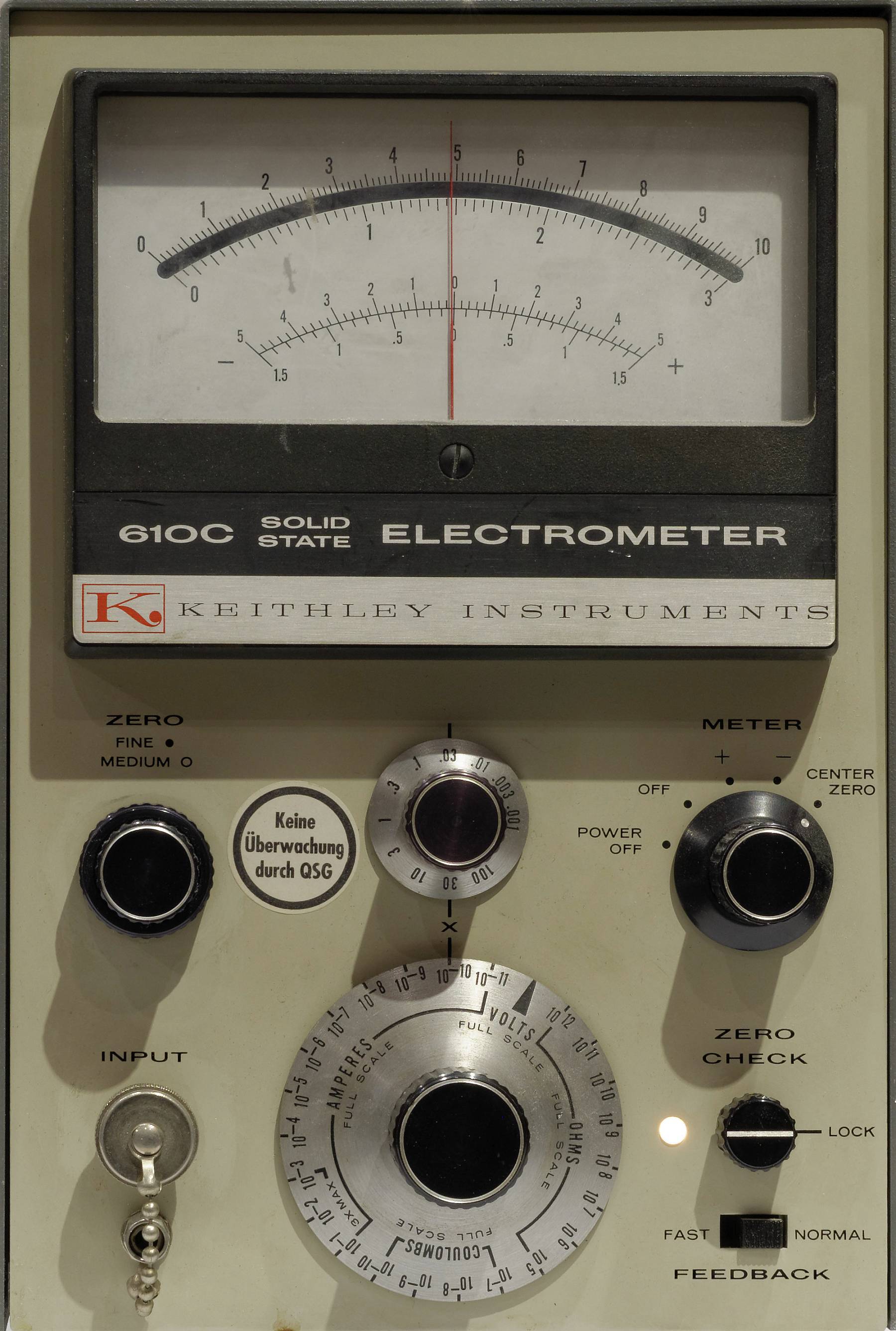
Keithley 610C, frontal view (desktop enclosure, a rack version was also made)
(click images to enlarge)
The Keithley 610C is a versatile electrometer. While a classical electrometer is simply a DC voltmeter with very high input resistance, the 610C can additionally measure very low currents, high resistances as well as charges:
- 11 voltage ranges, 1 mV to 100 V full scale (× 1 / × 3 steps)
input resistance >1014 Ω or selectable 10 Ω to 1011 Ω in decade steps
accuracy 1% of full scale, noise 25 μV
zero offset drift <1 mV per day / 150 μV per °C - 28 current ranges, 10-14 A to 0.3 A full scale
- 25 linear resistance ranges, 100 Ω to 1014 Ω full scale
- 17 charge (coulomb) ranges, 10-13 C to 10-3 C (Amprere-seconds) full scale
- Positive, negative and center-zero display modes
The unit has two sets of outputs on the back panel — one to attach a DVM or recorder, with +/- 3 V or +/- 1 mA full scale; this output is using a special connector, unfortunately. The other output (marked "× 1") tracks the input voltage. It is therefore possible to use the 610C as an amplifier, with a bandwidth of 40 kHz at × 1 down to 100 Hz at maximum amplification.
The input connector is a PL259 socket ("UHF plug", widely used in ham radio). This choice reveals the age of the 610C's design that hails from the vacuum tube era. Contemporary electrometers use triaxial input connectors, with the inner shield (guard) driven by an amplifier to be at the same potential as the input, in order to minimize leakage currents. It is possible to use a guarded input connection on the 610C through an adapter, although the guard potential is only available on the back of the instrument, at the "× 1" output. (Confusingly, there is also a terminal there labelled "guard", which is at input ground potential.)
When set to the "Normal" feedback, the 610C measures currents through the voltage drop across a shunt resistor. The large range switch selects the shunt resistance in decade steps between 10 Ω and 1011 Ω. Since only the voltage is measured, these shunts can also be used as defined input resistances in Volts mode (1 / current range), for example in the 1 nA (10-9 A) range, a 1 GΩ resistance is connected across the input.
In "Fast" feedback mode, the current range resistor is connected between the amplifier output and the input, turning the instrument into a feedback amperemeter (transimpedance amplifier) and reducing the input voltage burden to less than 100 μV. (Modern pico/nanoamperemeters work this way.)
Because there is very little (change of) input voltage, the meter's input capacitance has no effect, and the meter responds faster, hence the name.
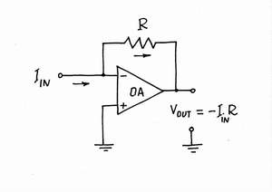
transimpedance amplifier (I to U converter)
In the Coulomb ranges (only valid in Fast mode), a capacitor takes the place of the feedback resistor, the instrument integrates input currents and thereby measures charge in Ampere-seconds (Coulombs).
Construction
The 610C is of an elegantly and perhaps deceptively simple design. At the core of the instrument is an operational amplifier with MOSFET inputs that is constructed from discrete transistors and works with +/- 120 V supplies, allowing it to measure voltages of up to 100 Volts in either polarity without needing the resistive input divider that is commonly found in electronic meters.
Note that the "× 1" output on the rear follows the input voltage within the full range, i.e. when the input is at +100 V, so is that output — but while you may not notice much when touching the 100 V at the input if it comes from a high-impedance source, the output has much lower impedance. Beware!
The opamp has a three-level zero adjustment, with switches for coarse and medium levels, and a 10-gang potentiometer for fine nulling. Zero drift is fairly low once warmed up, especially compared to the predecessor units like the 610B which still relied on electrometer vacuum tubes in the input stage.
The 610C contains only 10 transistors and 2 MOS FETs altogether, which are all used for amplification. The power supply is regulated using only a handful of Zener diodes.
The real effort is in the detail, however:
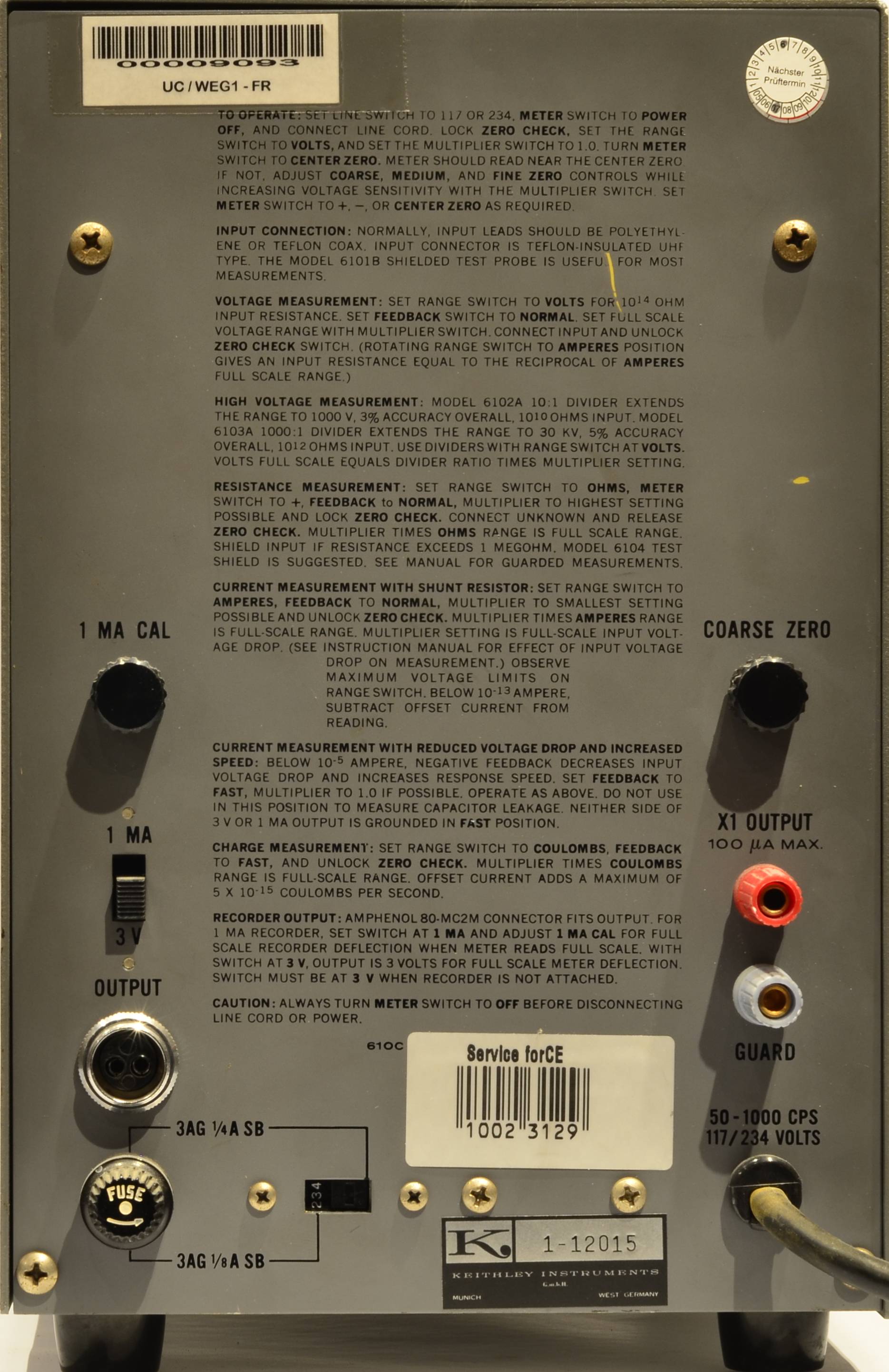
Keithley 610C, back view
Instructions are printed on the case!
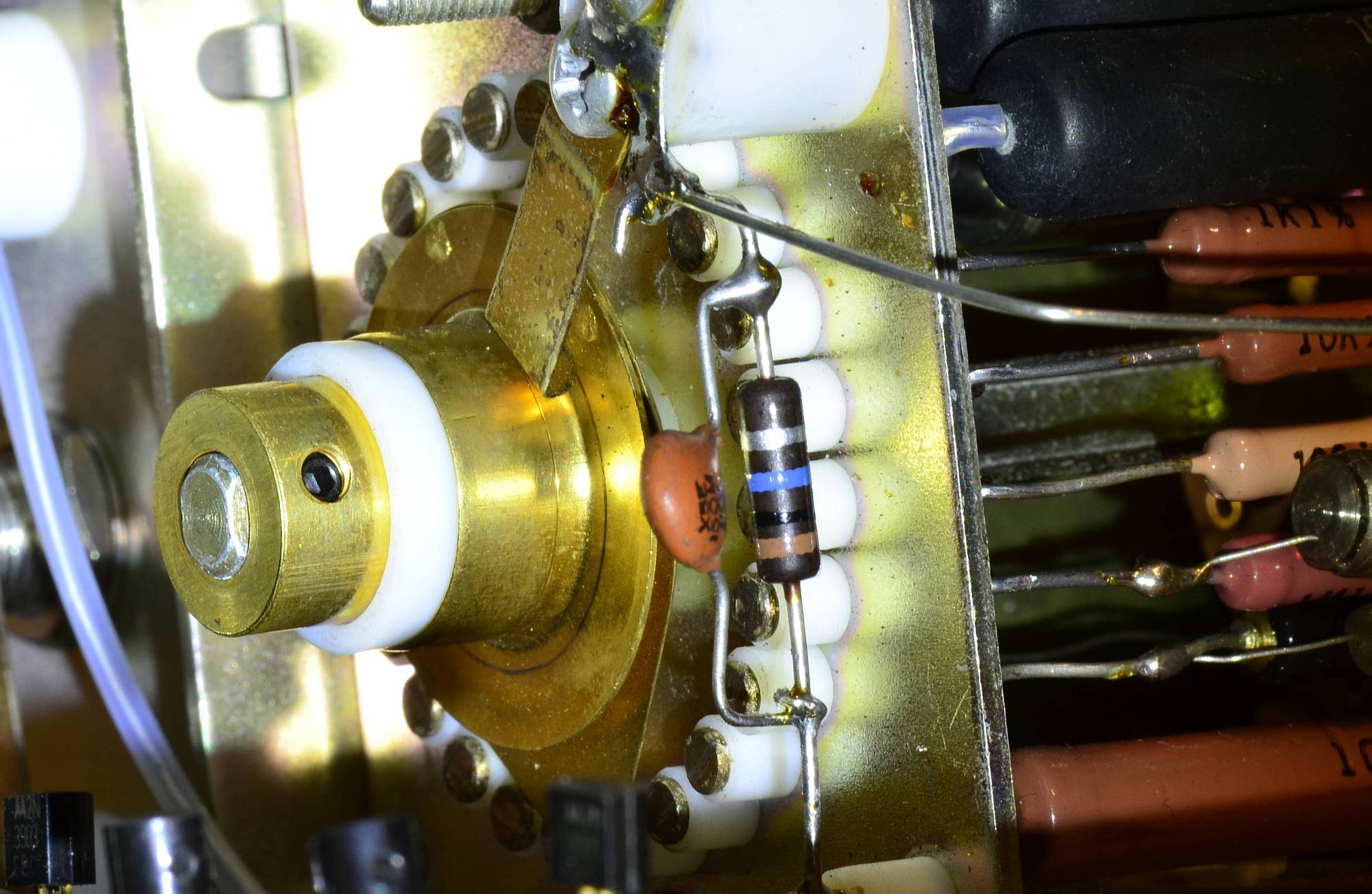
Range selector switch with teflon insulated contacts. This would probably be the hardest part to source today ... manual shows this was manufactured by Keithley themselves.
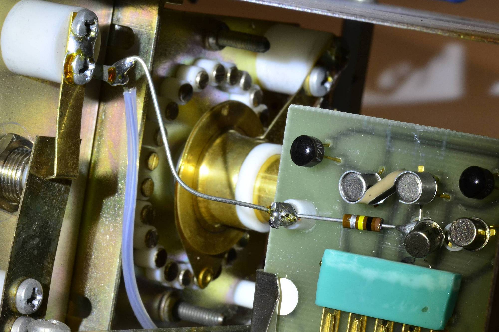
Input stage. The MOSFETS are thermally coupled. The input signal is routed over the top of the circuit board using teflon standoffs and a superior insulator (air). To the left, the zero switch can be seen.
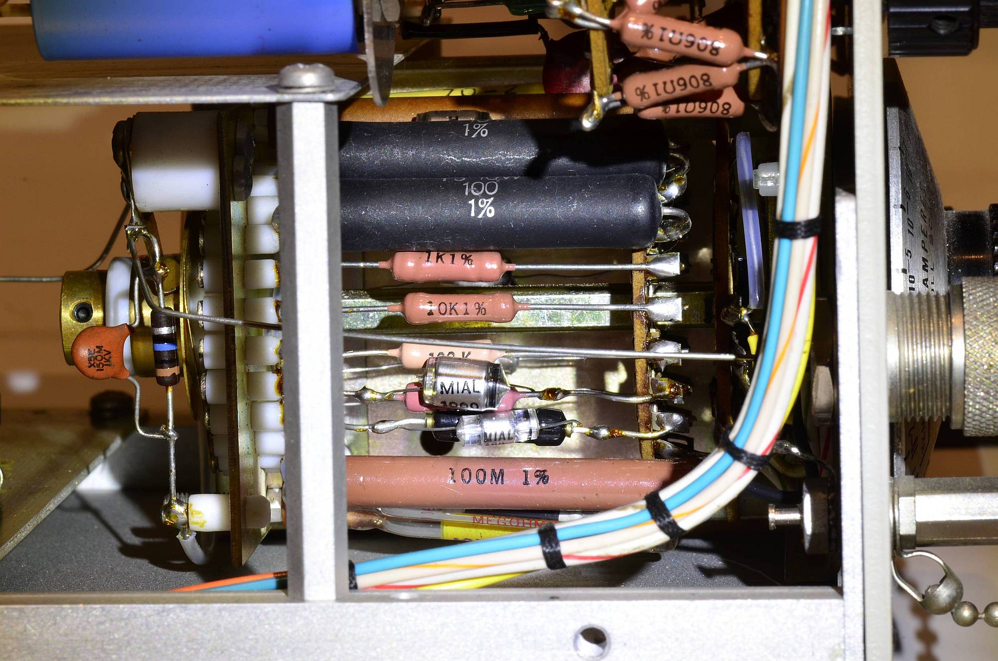
Range resistors, from 10 Ω to 1011 Ω.
Yes, there are 100 GΩ resistors in the form of a single component! (The parts list shows these were
made by company Victoreen. Today, Ohmite produces single resistors up to 10 TΩ!)
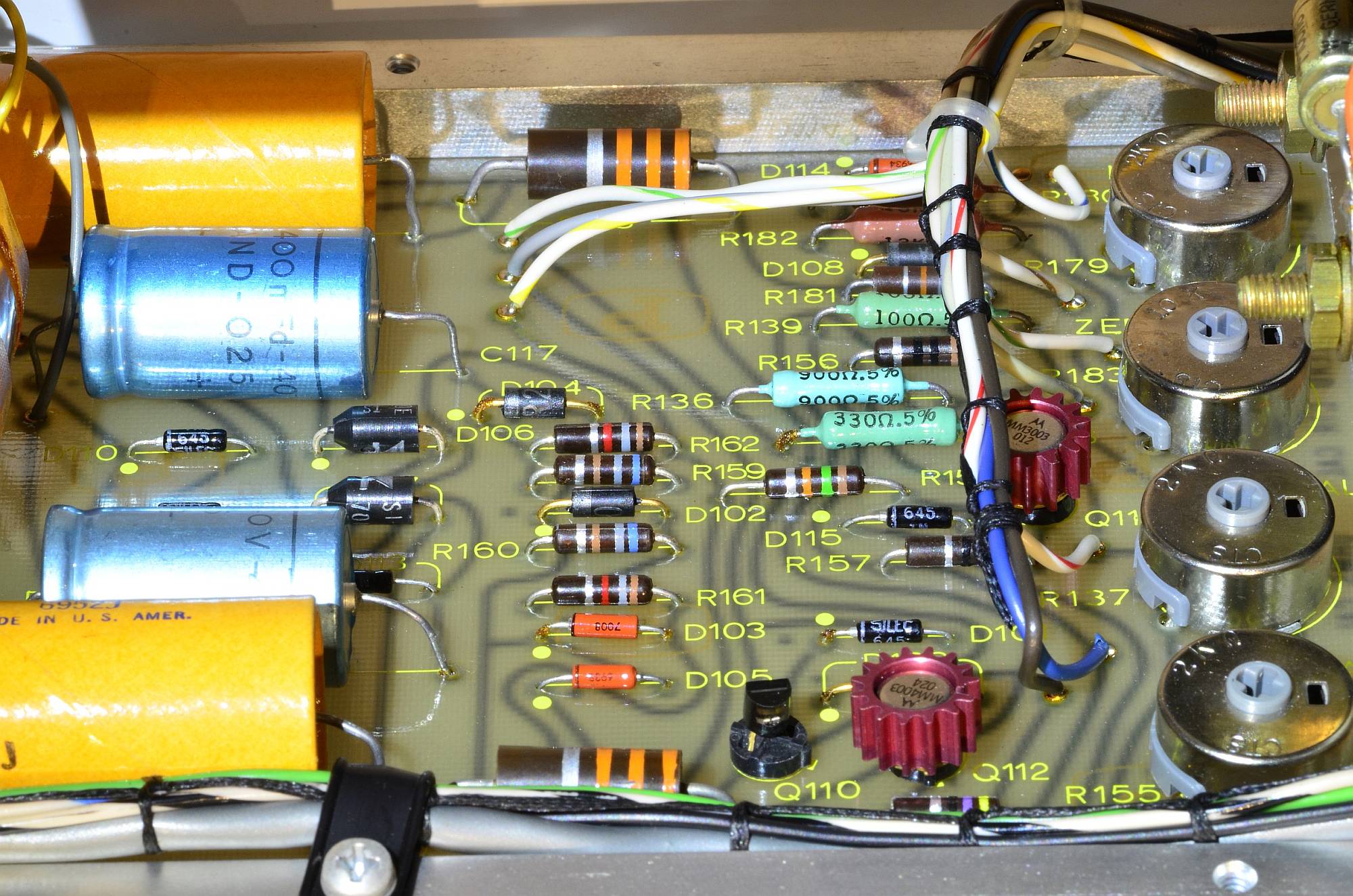
Output stage and power supply
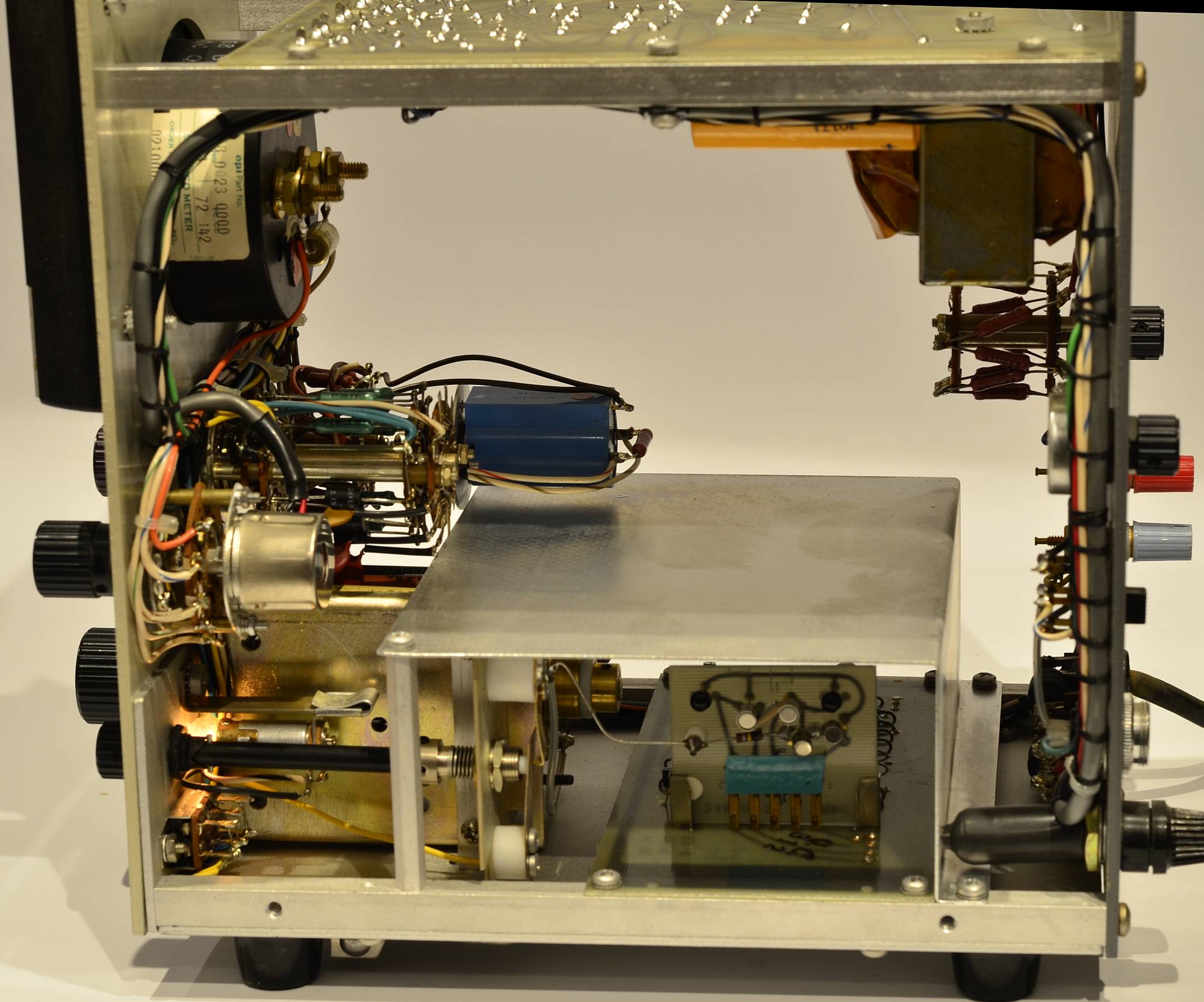
Interior view. Power supply/output board on top, input stage bottom center.