HP 59501A Isolated Power Supply Programmer (1973)
HP 59501A Isolated Power Supply Programmer
(click images to enlarge)
The HP model 59501 is a digital/analog converter with HPIB interface. It has two output ranges under software control (0–1 V / 0–10 V) and can supply 10 mA.
A switch in the back selects unipolar or bipolar output. The output is galvanically isolated from ground and HPIB.
The 59501 was intended to add an HPIB interface to power supplies with analog programming connections, but it can also be used stand-alone.
Meanwhile a good scan of the 59501B manual is available at archive.org.
The back panel carries the usual power and HPIB sockets as well as the HPIB address DIP switch, plus the uni/bipolar switch and a block with 6 screw terminals for the outputs.
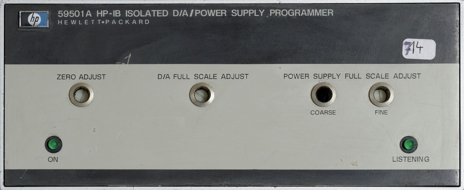
Output post A1 is analog ground, A2 is the voltage output. Zero and full span voltages can be trimmed through 10-turn potentiometers on the unit's front.
In addition, the 59501 contains another pair of 10-turn pots connected in series (coarse/fine) that are intended to set the full scale voltage of the attached power supply, where this is necessary or desirable for connecting the particular supply model.
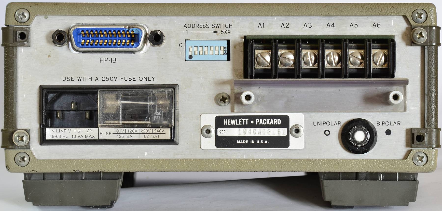
HP 59501A, rear view
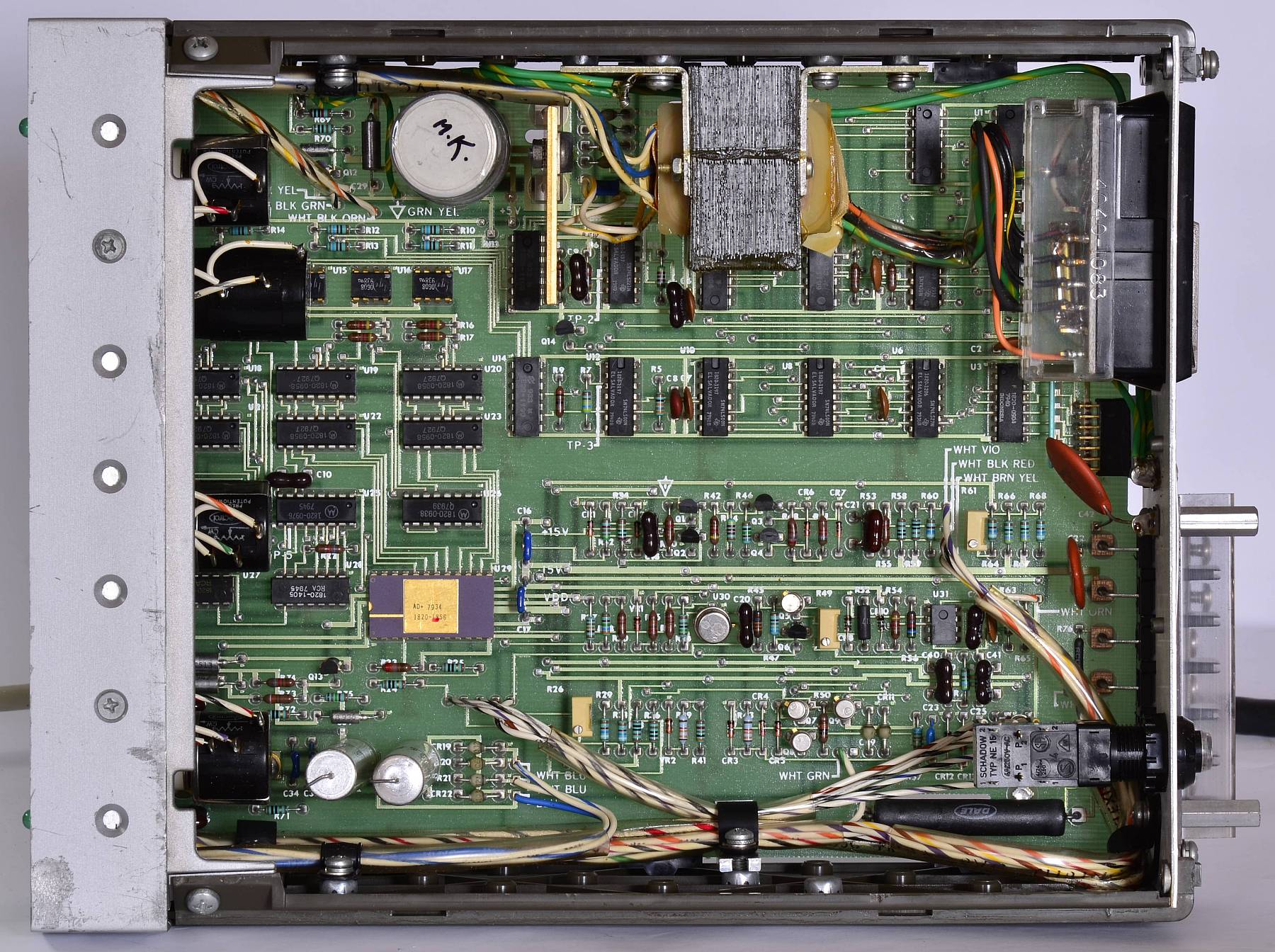
HP 59501A, interior view
The 59501's main circuit is built only from low-integration TTL ICs – there are no chips more complicated than the 7485 (4 bit comparator) or 74138 (3-to-8 decoder).
From today's perspective, the 12 bit D/A converter is an oddball type, having BCD-coded inputs. Such devices have since become extinct, what with microcontrollers in every corner – but remember, even the slow little Intel 8048 only came out in 1976, half a decade after the 59501 was designed.
With the ADC providing decimal steps (3 digit inputs), a lot of cumbersome re-coding was avoided elegantly. Programmers on such limited HPIB controllers as the HP 9830 will have approved!
The analog section is isolated from the digital bus interface through optocouplers. Of each digit, 4 bits are transferred in sequence as the digits are received, stored on the isolated side, and latched into the ADC with the last digit.
Controlling the converter via HPIB is easy – only 4 digits need to be sent. The first digit ("1" or "2") selects the 1 V or 10 V range, respectively. The following three digits ("0"-"9") directly control the output voltage. In bipolar mode, 000 produces the maximum negative output voltage, 500 = 0 V and 999 produces the maximum positive output.
However, due to the minimalistic decoding of input characters, the 59501 will also interpret characters outside the "0"–"9" range as digits — unfortunately, this is also true for carriage return and line feed characters.
Therefore, if e.g. in an HP-85 program, the 59501 (assumed on interface 7, HPIB address 14) were controlled with
the computer will silently add CR LF to the end of the string, and the 59501 will output an incorrect value. There are several ways to sidestep this issue, one of them being to send the command "manually":
This code explicitly addresses the 59501 (Unlisten, My Talker Address, Listen Address 14) and sends exactly 4 data bytes to the unit.
A more elegant solution uses a feature of the OUTPUT USING statement that is a little hidden in HP's documentation – prefixing the format string with # suppresses the line feed:
This and many more details are described in a Programming Note for using the HP59501A with the HP-85.