Hewlett Packard 3325A Synthesizer
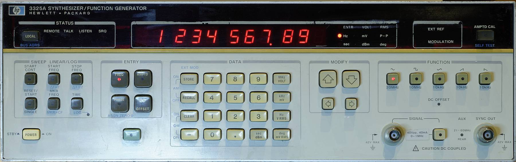
Hewlett Packard 3325A Synthesizer
(click images to enlarge)
The manual is available from Didier's great collection.
The HP3325 is a synthesized function generator that can produce sine wave voltages of 1 Hz to 21 MHz (up to 60 MHz ugly sine from back panel), square wave signals up to 11 MHz, or triangle / sawtooth signals up to 10 kHz. The frequency can be specified with up to eleven digits of precision! (Internally, the 3325 uses 15 stages of BCD counters. Up to 100 kHz the resolution is 1 μHz, and up to 10 MHz it is 1 mHz.)
This is one of the first instruments to use a "fractional–N" PLL synthesizer. The output frequency is derived from a reference frequency which can also be supplied externally.
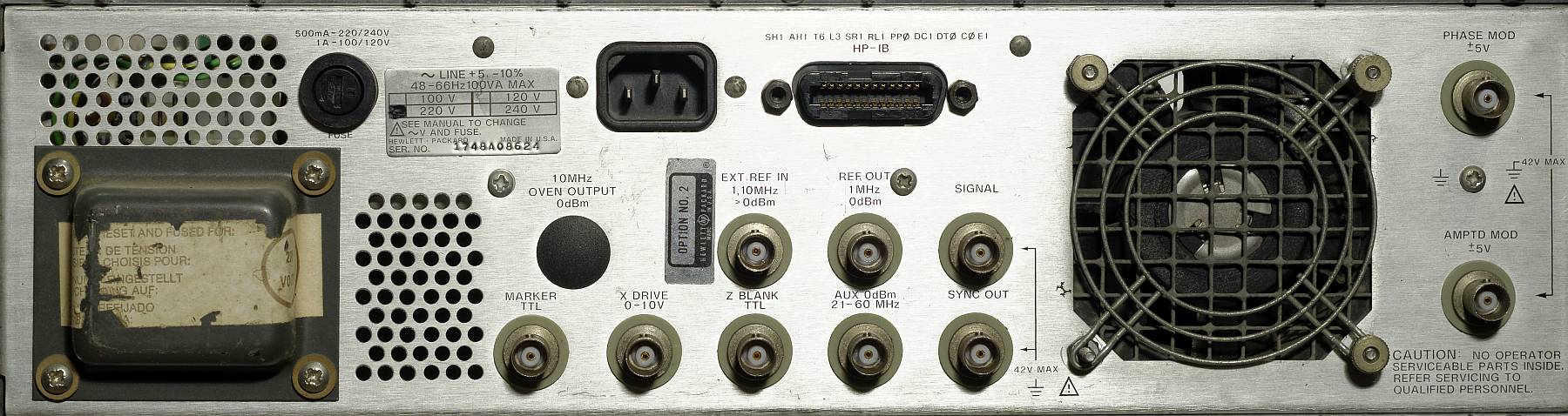
Hewlett Packard 3325A back panel
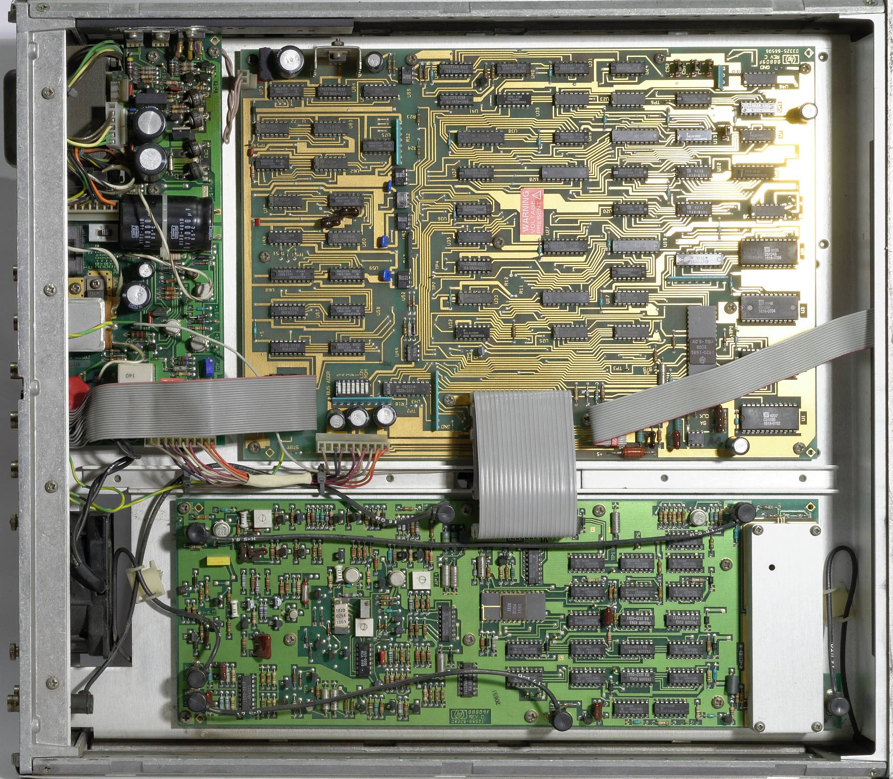
HP 3325A interior (from top)
Power supply (left), processor board with HPIB (top)
One of the first things to notice about the 3325 is the relatively low weight, which comes as a bit of a surprise given the voluminous case (and experiences with other HP instruments of similar size).
Internal construction is simple and clear. A central chassis carries circuit boards above and below, and there are no voluminous or heavy parts other than the mains transformer.
HP offered two major options on this unit: Opt.001, a high-stability crystal oscillator (OCXO), and Opt.002, the "High Voltage Output" which is a separate amplifier that can supply 40 Vss into a 500 Ω load up to 1 MHz.
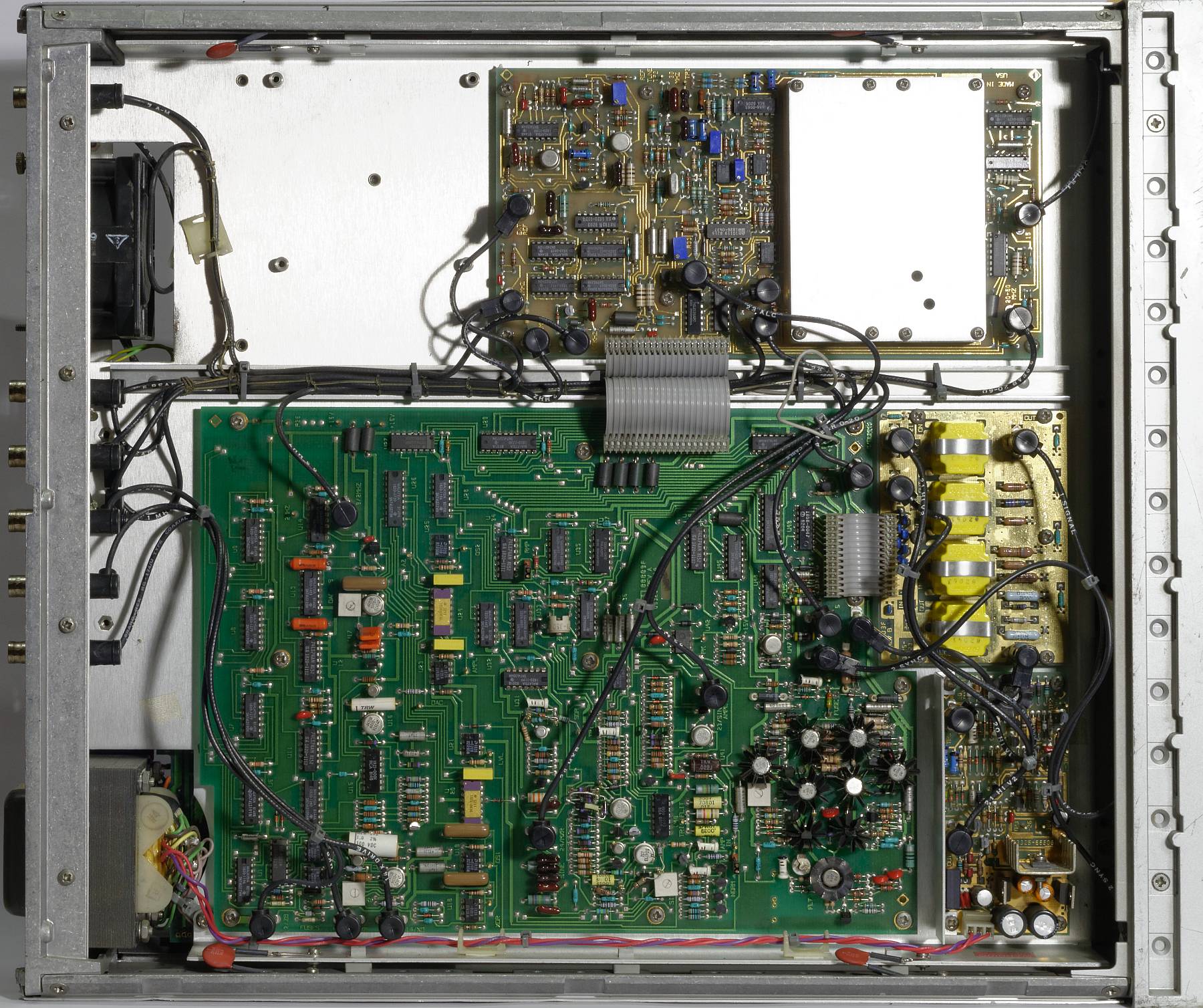
Hewlett Packard 3325A interior (from bottom)
The unit pictured here has Option 002 installed (small PCB at bottom right).
The OCXO (Opt.001) would fit into the vacant area to the top left.
The mains transformer is permanently connected to the line so that the OCXO can be kept powered on at all times, and the nominal output frequency is available without waiting for warm-up. As a consequence, even the pictured unit without Opt.001 already consumes 9 W just plugged in, in operation this rises to about 75 W (somewhat dependent on load).
The 3325 was developed in the late 1970s (→ HP Journal 01/79). Remarkably, it already came with an HPIB (aka GPIB, IEEE488, or IEC Bus) Interface built in. This interface is built from individual TTL SSI components and opto-couplers. Programming commands are simple 2- or 3-letter acronyms like "FR123456HZ" = set frequency to 123456 Hz. In this generation of bus-connected test equipment, the commands were device specific — SCPI standardization (e.g. "SOURCE:FREQUENCY 12345 Hz") was only to happen years later.
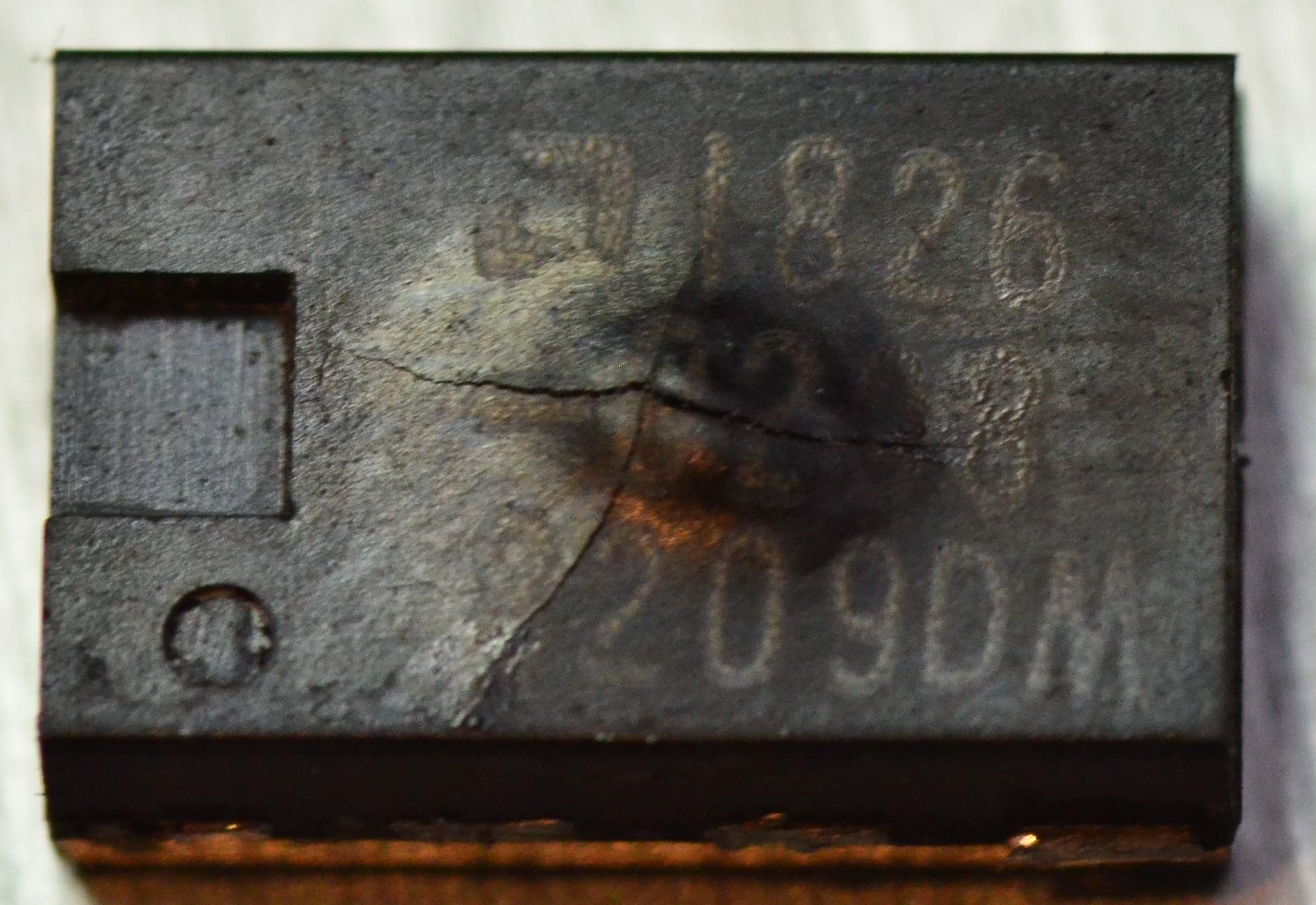
Interestingly, the 3325's CPU is not an "off the shelf" microprocessor/microcontroller even though a variety of suitable chips had been on the market since the mid-1970s (8080, 6502 and many others). Instead, HP used a proprietary microcontroller only known as "1820-1691", designed and produced by HP itself. This chip can also be found in a number of HP computer peripherals of the 98x5 desktop computer era, such as diskette drives or printers. Officially called a "Nanoprocessor", the chip was manufactured using an NMOS process, which among other things means that it needs a negative bias voltage in addition to the regular +5 V supply. The required bias voltage was apparently somewhat variable between production runs, so the correct value was stamped or even hand-written onto every chip. In case the processor needs to be replaced, the technician may have to modify a voltage divider on the main board!
Until recently, little information on the processor was available online. Then, a Nanoprocessor User's Guide (1975) turned up, and in September 2020, Ken Shirriff published two articles on the chip, Inside the HP Nanoprocessor: a high-speed processor that can't even add and a second that details his complete reverse engineering effort.
The nanoprocessor was used in interfaces for the 9825/9835 desktop comnputer series, and test equipment like the 4262A LCR Meter. In the 3325, the Nanoprocessor was combined with two "huge" RAMs (256x4 bit!) and (at least in the earlier production units) four mask-programmed(!) ROMs holding the firmware. Apparently, the developers then still had sufficient time for debugging ...
Repairs
The unit pictured here, manufactured in early 1982 judging by the date codes on the various chips, worked almost out of the box. The usual problems with sticky keys were easily solved (no pun intended) using alcoholic cleaner and a little exercise.
Initially, the unit tended to lock up soon after power on if more CPU intensive tasks were executed (e.g. a logarithmic sweep). This problem disappeared after warm-up. It turned out that the +5 V supply near the CPU was a little low at 4.9 V even though the power supply produced 5 V straight. There is a relatively high drop across a choke on the CPU board that I will likely replace in the long run. A tiny increase of the supply voltage fixed the issue.
Resuscitation #1
After several hours of patient operation, the 3325 died unexpectedly, with a faint odour of hot plastic. A quick check found the power supply being loaded down and the 15 V series regulator becoming very hot; with the logic board unplugged, the voltages were OK. Oh no, not the CPU please, it's practically unobtainable ...
Disconnecting the internal boards one by one quickly identified the output board as the location. Maybe the output stage? There are two solder links for the +/- 15 V supplies to the output stage, cutting these made no change however. Oh well, get the magnifier in. Sure enough, there's a dead opamp (U25).
Cross-reference parts lists identify it as an LM310 x1 buffer. No need to despair: The pinout is the same as a 741, which specification-wise will do fine here. Some caring soul at HP even left the trace between pin 6 (output) and pin 2 (inverting input) on the board which the 310 wouldn't need, having no inverting input. With a 741 (I even had a spare one with '82 date codes, hee hee) and new solder links, the 3325 is happy again.
Dead buffer amp (U25)
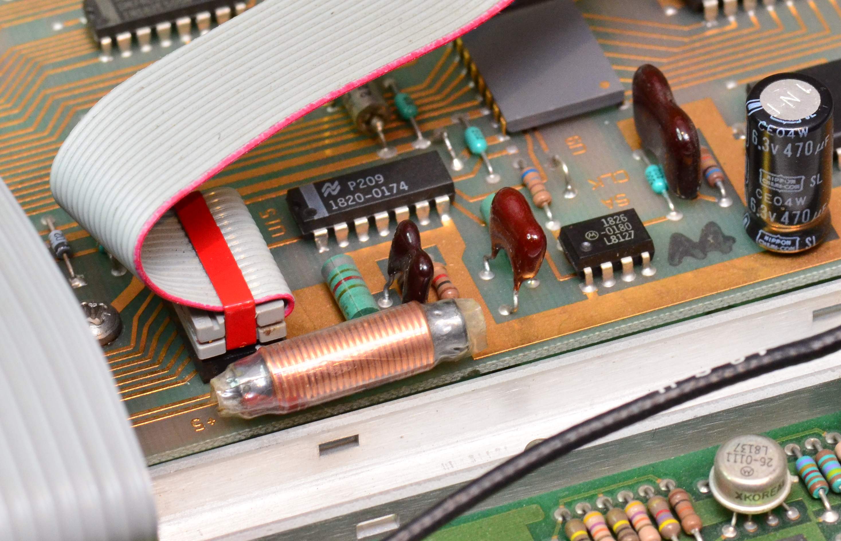
Uprated (4 A) choke installed on processor board, now drops only 50 mV.
Another thing that irks me about the 3325 is that the poor little reference crystal is located right in the main airflow path from the rear fan. Clearly the design was for a "function generator" class instrument (5 × 10⁻⁶ specified). If you wanted real stability you'd have to order Opt. 001. A small styrofoam baffle should at least improve short term stability a little. It did make frequency trimming a bit easier, although putting the bottom cover back on still offsets the frequency quite a bit.
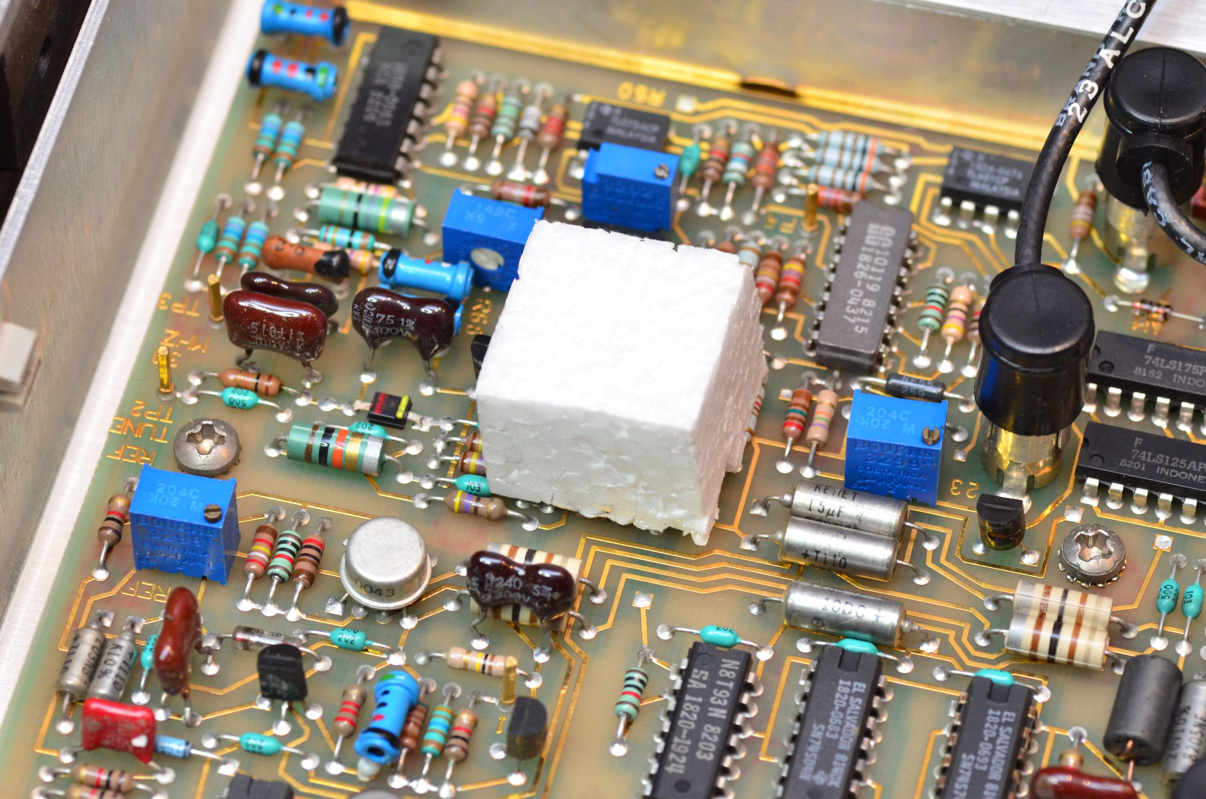
Styrofoam baffle for the reference crystal
Resuscitation #2
Especially since that choke was installed, my 3325 has had cold start problems (literally related to temperature). Some experimentation shows that apparently the processor won't reset cleanly. First let's check that -5 V supply that the CPU needs. This one has "5.0 V" printed on top, but the actual VBG on pin 38 is just -4.7 V. Eureka? A 120 kΩ resistor from -15 to -5 fixes that quickly. Nice try, no cigar however – it still won't reset reliably.
Well then, how does this thing reset in the first place? According to the schematic from the manual and the pinout diagram, there is no reset pin?! After some research, I stumble upon a mailing list posting from 2001 that mentions that the +9 V supply to the CPU chip (VGG on pin 40) serves as a reset when missing. Ouch.
Apparently, replacing that choke upset the power supply sequencing. An extra 47 μF in parallel to C6 (pin 40 to ground) seems to do the trick.
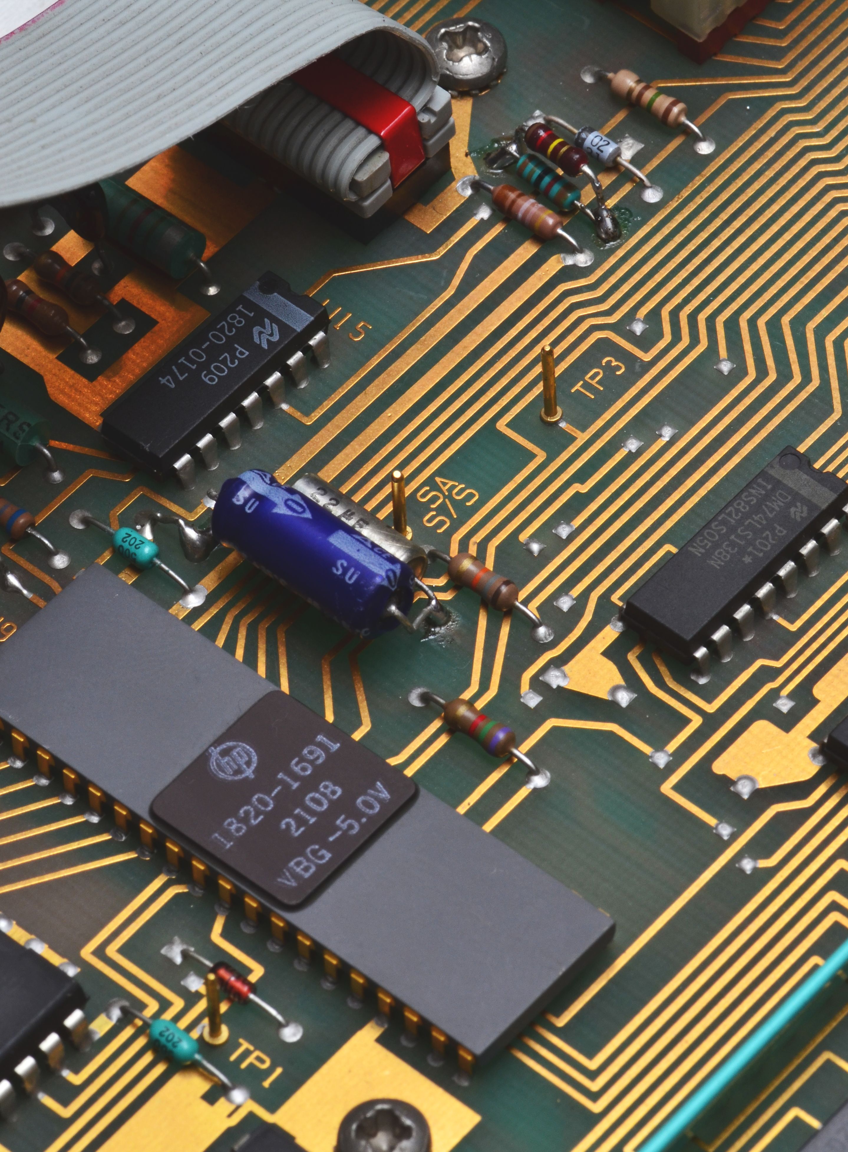
-5 V correction (top) and reset capacitor (center)